Start with the part, then choose the process
Sheet metal bending gives a flat sheet a permanent angle or curve. On a press brake, a punch and die form a bend along a line; this page focuses on conventional V-die bending. The finished part depends on the material, radius, contact method and dimensions, as well as the angle. For a continuous curved profile, compare roll bending instead. Compare the available routes in the process overview.
A press brake can form the angle on a drawing while still producing the wrong part: the flanges may be the wrong length, a nearby hole may distort, or the last bend may trap the part against the tooling. Treat a bend as a linked problem involving geometry, material, tooling and verification. Start with the method and contact below, then check radius, tool support, load and clearance before preparing a trial bend.
For a first review, collect the drawing revision, material grade and condition, actual thickness, finished angle and inside radius, dimensional datums, tolerances and bend length. Mark the visible face, rolling direction if known, nearby cut-outs and any return flange. A missing radius or unspecified dimensioning convention is a question to resolve, not permission to guess.
Understand the contact before changing a setting
In air bending, the sheet is supported at the two die shoulders and loaded by the punch. It is not fully enclosed between matching tool faces. Changing punch penetration changes the bend angle. The resulting radius depends on the material and tool arrangement; it cannot generally be read straight from the punch nose. In conventional air bending of mild steel, the die opening is a major influence on the natural radius. Do not extend that statement to every high-strength grade or large-radius setup. [R1, R4]
| Method | How the shape is established | Preparation consequence |
|---|---|---|
| Air bending | Punch penetration and a partially supported sheet | Check opening, expected radius, load and room for springback compensation together. |
| Bottom bending | The sheet engages the matched punch and die faces | Verify the specified tooling and higher force requirement; do not use an air-bending estimate unchanged. |
| Coining | High local pressure impresses the tool shape into the bend and can thin the material. | Review this process separately with the machine and tooling supplier; an air-bending force estimate does not establish a coining setup. |
Bottoming brings the sheet into contact with the matching tool faces; coining additionally presses into the material and can reduce its thickness. They are not two names for the same method, nor settings reached simply by adding force to an air bend. A process change calls for a fresh load and tooling review. The rest of this page develops air-bending preparation, not coining or special-tool operating settings. [R2, R10]
Read the dimensions using one convention
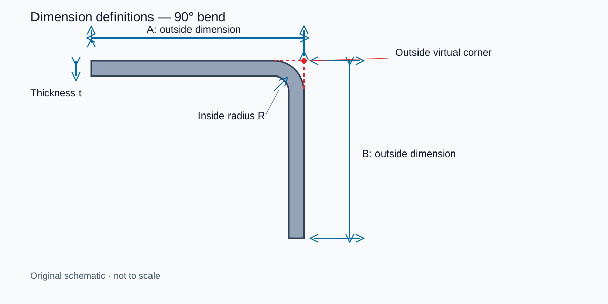
Use t for actual sheet thickness and R for the finished inside radius. The bend angle α is the rotation from the original flat sheet; the included angle β is the angle between the finished legs. Under this convention α + β = 180°. A right-angle part has α = β = 90°, which hides the distinction. A part with a 120° included angle instead uses a 60° bend angle. Confirm the calculator convention before entering either number. [R5]
For the worked example below, A and B are outside dimensions measured to the virtual sharp corner: extend the two straight outside faces until they intersect. Neither A nor B is the straight length ending at a bend tangent. Mixing these dimensions gives a wrong blank even when the formula itself is correct. Compare these conventions in bend allowance and bend deduction.
Choose a die by checking the constraints together
What is the minimum bend radius? Thickness alone cannot answer that question. Keep four quantities separate: the inside radius required by the drawing, the actual inside radius after unloading, the applicable minimum radius in the material guidance, and the punch nose radius. First establish whether a supplier’s limit describes the finished inside radius or the punch radius; a minimum punch radius alone does not approve the part’s finished radius. [R1, R4]
| Check in order | What the answer must establish |
|---|---|
| Material and condition | Identify the grade, delivery condition and actual thickness. |
| Applicable guidance | Match thickness range, bend-line direction and forming method; confirm which radius the recommendation defines. |
| Tool arrangement | Check punch radius, die opening and contact conditions against that guidance. |
| Finished part | Measure the unloaded inside radius and inspect the bend and edges for cracks using representative trial material. |
If the applicable radius or tooling conditions are unknown, keep them open for verification. R/t is a useful ratio, not a universal acceptance limit. A predicted natural radius and a material’s minimum permissible radius answer different questions.
| Check | What to establish | If the check fails |
|---|---|---|
| Inside radius | The material and tool combination can produce an acceptable finished radius. | Review the opening, punch and material guidance; do not force a tight radius by adding load. |
| Flange support | The short leg remains adequately supported during the bend. | Review another opening, special tooling or the part design. |
| Load | Required total force and line load fit the machine, punch, die and holders. | Review the process with the equipment and tooling limits. |
| Surface and cut-outs | Contact marks and nearby hole distortion meet the drawing requirements. | Review protection, tool contact or feature placement. |
| Clearance | The part can be located, bent and removed at every stage. | Simulate another sequence or review the tool profile and machine geometry. |
For otherwise comparable conventional air-bending conditions, a wider V opening generally reduces force but changes the radius and flange-support requirement. A smaller opening may help a short flange while increasing the required force. Use the actual tooling supplier recommendations rather than one thickness multiplier for all materials. A short flange, a nearby hole and a closed-box shape are separate constraints, not three names for a tonnage problem. [R1, R7, R8, R9] For an initial opening check, use the V-die opening calculator.
When the part geometry, tooling and force requirements are clear, compare Press brake machines for the planned bending work.
Separate springback, cracking and blank-length errors
Springback is elastic recovery after the load is removed. The loaded angle and unloaded finished angle therefore need separate records. Overbending can compensate, but the tool angles and available travel must permit it. A compensation value is meaningful only with its material and setup. SSAB discusses increasing recovery with steel strength and die-width/thickness ratio; its numerical predictions are product-specific, not universal correction angles. [R3] Continue with springback and angle compensation.
For cracking, review the grade and condition, requested radius, bend-line orientation, edge quality and surface damage. Write “bend line parallel/perpendicular to rolling direction” rather than an ambiguous grain label. SSAB recommends a transverse bend line where possible in its Hardox/Strenx workshop guidance; check the actual grade recommendations before applying that direction to another material. Changing the blank nesting orientation is a process change. [R4] Check grade and condition in the materials guide.
A correct angle with incorrect leg lengths needs a dimensioning and blank-length check. K factor describes the neutral-axis position used in the unfolding model; it is not a springback setting. Record the measured angle and radius before treating K as the cause of a dimensional error. [R5, R6]
Work through one 90-degree blank-length example
This is a teaching example, not a tested material recipe. Assume t = 2.00 mm, finished R = 2.00 mm, bend angle α = 90°, K = 0.40, and virtual-corner outside legs A = 50.00 mm and B = 30.00 mm. The K value is an explicit assumption; it is not assigned to any grade or die. [R5; example assumptions]
| Quantity | Calculation | Result |
|---|---|---|
| Bend allowance BA | (π/180) × α × (R + Kt) | 4.398 mm |
| Outside setback OSSB | (R + t) × tan(α/2) | 4.000 mm |
| Bend deduction BD | 2 × OSSB − BA | 3.602 mm |
| Flat length L | A + B − BD | 76.398 mm |
Check it a second way: each straight tangent length is shorter than its outside leg by 4.000 mm. Thus L = (50 − 4) + (30 − 4) + 4.398 = 76.398 mm. BA is added to the two straight portions; BD is subtracted from the two virtual-corner outside dimensions. They are different quantities. The displayed precision shows arithmetic and does not specify a production tolerance.
If only the assumed K changes from 0.40 to 0.44, the predicted flat length becomes 76.524 mm: a difference of 0.126 mm. This calculation isolates one variable; a real tooling change can change the finished radius too. Enter these inputs in the bend deduction calculator, then replace assumptions with trial measurements before cutting the production blank.
Bend deduction calculator
Reproduce the example using explicitly defined outside dimensions.Press brake tonnage calculator
Estimate force, then check the actual machine and tooling ratings.
Turn a trial bend into a usable process record
Use a specimen representative of the intended material and setup. Establish the final unloaded angle and inside radius, verify the dimensional convention, then compare the measured blank length and leg dimensions. Build a bend table only from measured, identified conditions. Autodesk distinguishes supplied formula-based example tables from tables calibrated to a particular machine and tooling. [R6]
| Record | What to retain |
|---|---|
| Part and material | Drawing/revision, grade/condition, batch identity, actual thickness and rolling direction. |
| Tooling and setup | Machine/program revision, punch/die identifiers, V opening, orientation, bend length and approved load limits. |
| Starting geometry | Measured blank length, datums, target angle/radius and dimension definitions. |
| Measured result | Unloaded angle, inside radius, A/B dimensions, surface and hole condition, measurement method. |
| Decision | Correction made, new result, accepted process revision and who approved release. |
For this 90° example, an empirical BD is A + B − L. If the same specimen actually measures A = 50.00 mm, B = 30.00 mm and L = 76.39823 mm, BD is 3.60177 mm. With independently measured R = 2.00 mm and t = 2.00 mm, BA = 2(R + t) − BD and K = [BA/(π/2) − R]/t recover approximately 0.40. These are hypothetical measurements demonstrating the method, not shop test results. A wrong radius measurement will corrupt the inferred K.
The trial-bend guide develops the setup, measurement and correction workflow; use it to connect the geometry calculation to a measured sample. Continue with the trial-bend procedure.
Use the symptom to choose the next check
| Observed symptom | Checks to prioritize | Evidence needed before changing the process |
|---|---|---|
| Angle opens after unloading | Angle convention, springback and permitted overbend | Loaded/unloaded definitions, final angle and setup record. |
| Angle correct, legs wrong | Datums, backgauge location, outside/tangent definitions, blank and unfold rule | Actual blank length, A/B, angle and radius from the same part. |
| Outside surface cracks | Material condition, radius, bend-line direction and edge damage | Grade guidance and inspection of the crack location and specimen. |
| Hole or slot distorts | Feature position relative to the bending zone and tool support | Drawing location and a trial using the proposed method. |
| Last bend collides | Sequence, punch/holder profiles, open height and removal path | Offline collision review of each stage with actual tooling. |
Use the table to choose the next checks; several factors may act together. Resolve a collision or load concern through the approved setup review before another stroke. [R7, R8, R9]
Continue with the specific calculation or equipment decision
Use the calculators to document the assumptions, then carry the result into a trial-bend record. This article explains process preparation. Comparing machines, controls or automation belongs in the selection guides; machine acceptance and part acceptance require their own agreed criteria.