Bring the part into machine selection
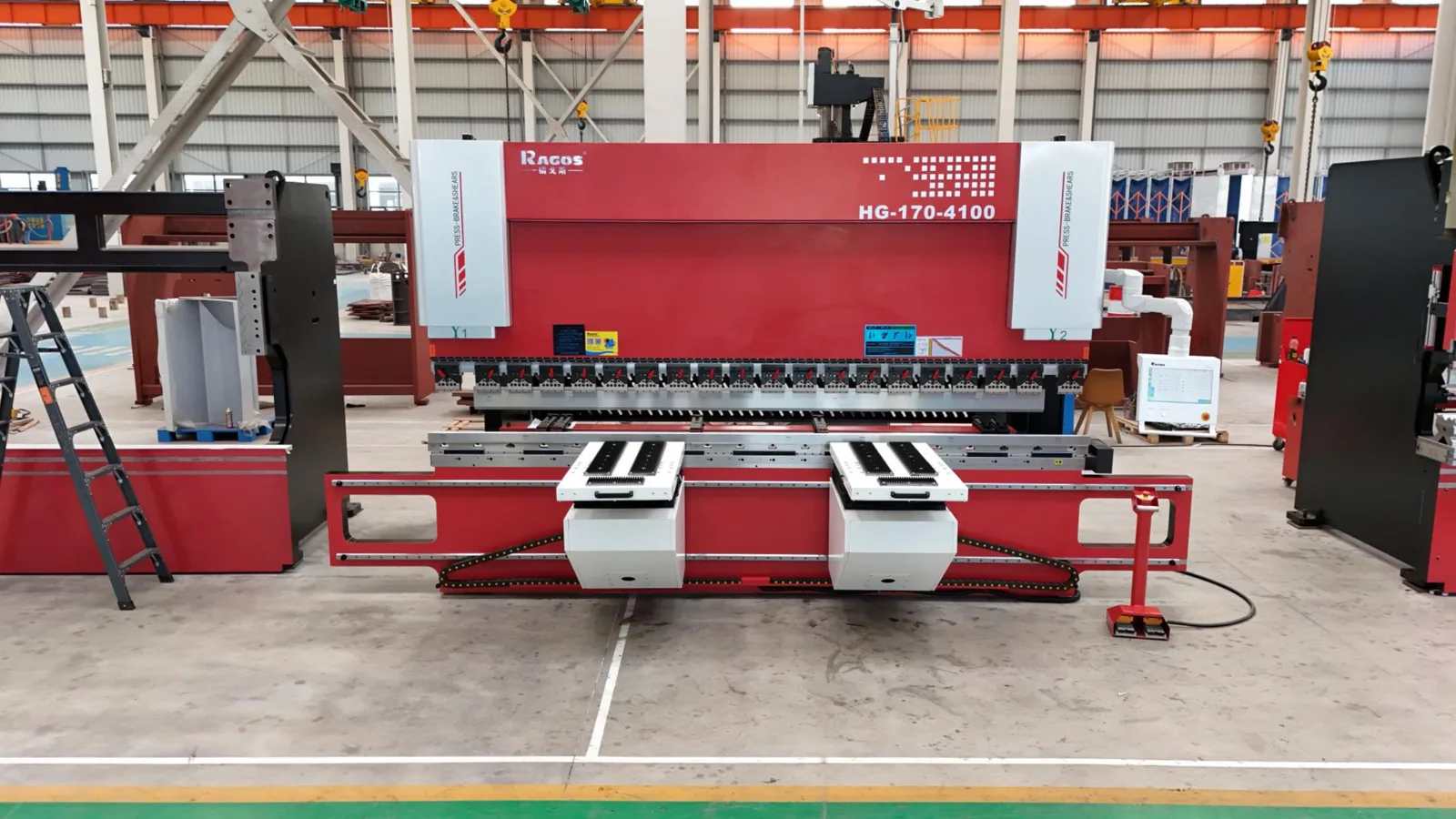
Tonnage is one part of machine selection. Bring the material grade, simultaneous bend length, part drawing and planned tooling to check working length, load distribution and tooling capacity. Also check stroke, daylight, throat and part clearance.
The air-bending tonnage formula
This empirical model estimates straight V-die air bending. Material strength enters through Rm; no extra material multiplier is applied. The coefficient 1.33 is empirical, not a capacity allowance.
Bending force: F [kN] = 1.33 × Rm × t² × L ÷ (1000 × V)
Meaning: F [tf] = F [kN] ÷ 9.80665
| Symbol | Meaning |
|---|---|
| Rm | Ultimate tensile strength, MPa (N/mm²); use the material certificate, not yield strength. |
| t / S | Actual sheet thickness, mm. |
| L | Length bent simultaneously in one stroke, mm; not the full blank size. |
| V | Actual die opening, mm. |
| F / P | Applied bending force, expressed in kN and metric tonnes-force (tf). |
| r / b | Inside radius and flange dimension shown in the geometry; neither is an input to this force model. |
At fixed V, force varies with thickness squared. Doubling length or tensile strength doubles force. Automatic die selection also changes V, so compare thickness and opening together. L is entered in mm; when using metres, omit the factor 1000. This formula does not calculate radius, minimum flange or flat-pattern length.
How automatic V-opening is chosen
| Material | Thickness ≤ 10 mm | Thickness > 10 mm |
|---|---|---|
| Mild steel | 8t | 10t |
| Stainless steel | 10t | 10t |
| Aluminium | 6t | 10t |
Above 10 mm, automatic V is 10t for every preset. A 12 mm plate starts at V120, with no silent rounding to 125 mm. At exactly 10 mm the original material rule remains. These are factory-practice starting values; select Manual for your actual tooling.
Why can force fall just above 10 mm?
Mild steel changes from 8t to 10t and aluminium from 6t to 10t. The wider opening can lower force even while thickness rises; stainless remains at 10t. Hold V fixed to isolate thickness. Custom material keeps your entered tensile strength and uses a manual opening; above 10 mm the automatic 10t suggestion is also available.
Two worked examples, with the inputs included
Assumed inputs for both examples: mild steel, Rm = 450 MPa, straight air bending. The separate allowance starts at 15% and is editable from 0 to 30%; it never changes the raw bending force.
2 mm mild steel · One-metre bend
Meaning: Rm = 450 MPa; t = 2 mm; L = 1000 mm; V = 16 mm (8t).
Bending force: F = 1.33 × 450 × 2² × 1000 ÷ (1000 × 16) = 149.625 kN; 149.625 ÷ 9.80665 = 15.26 tf.
Average force per metre: 15.26 tf/m. Capacity target with 15% allowance: 15.26 × 1.15 ≈ 17.55 tf.
12 mm plate · Three-metre bend
Meaning: Rm = 450 MPa; t = 12 mm; L = 3000 mm; V = 120 mm (10t).
Bending force: F = 1.33 × 450 × 12² × 3000 ÷ (1000 × 120) = 2154.600 kN; 2154.600 ÷ 9.80665 = 219.71 tf.
Average force per metre: 73.24 tf/m. Capacity target with 15% allowance: 219.71 × 1.15 ≈ 252.66 tf.
Load either example using the buttons above; loading replaces the current inputs and clears previous trial measurements.
What happens when you change V-opening?
Hold 12 mm mild steel, 450 MPa and a 3000 mm simultaneous bend length constant. Only V changes. Lower force alone does not establish a suitable die; check part radius, flange dimensions and tool ratings.
| V-opening (mm) | Thickness ratio | Estimated force (tf) |
|---|---|---|
| 96 | 8t | 274.64 |
| 120 | 10t | 219.71 |
| 144 | 12t | 183.09 |
Press brake tonnage questions
Why does another calculator give a different result?
Compare tensile strength, actual V-opening, simultaneous bend length, empirical coefficient and force units. In this model a 2 mm, 450 MPa, 1000 mm bend needs about 20.34 tf at V12 and 15.26 tf at V16.
Is stainless steel always a fixed multiple of mild-steel tonnage?
Force scales with tensile strength only when thickness, length and V are held constant. Automatic V can differ between materials; material names alone do not establish the ratio.
Which opening is used at exactly 10 mm?
Mild steel uses V80, stainless V100 and aluminium V60. The shared 10t rule applies strictly above 10 mm.
Can I use this for bottoming, coining or hemming?
This equation estimates straight V-die air bending. Bottoming, coining, hemming, special tooling and non-uniform loads require a separate assessment.
Does bend angle or punch radius change this estimate?
There is no separate angle or punch-radius input in this model. Both still affect process feasibility, so sufficient calculated force does not replace a tooling-geometry check.
Can I choose a press brake from total tonnage alone?
Check working length, stroke, daylight, permitted load distribution and punch, die and adapter ratings as well. Force per metre is an average, not every local peak load.
At the same tonnage, can a shorter bend handle thicker sheet?
In theory, yes. At fixed material, actual V-opening and total estimated force, thickness varies inversely with the square root of loaded length. With 450 MPa mild steel and V24, 2 mm × 1000 mm and 4 mm × 250 mm both require 99.75 kN. Average line load rises from 99.75 to 399 kN/m. Check punch, die, holders, ram and bed capacity and whether the V-opening suits the thickness and part. Recalculate when V changes.
Short bends still require tooling and ram load checks
At fixed tensile strength, thickness and V-opening, total air-bending force is proportional to loaded length. Dividing force by the loaded bend length gives average line load. This is a comparison with documented limits for this setup, not a full machine approval.
Average load per metre of bend: q [kN/m] = F [kN] ÷ (L [mm] / 1000)
Assumed example: 12 mm mild steel, Rm = 450 MPa, actual V = 120 mm. A 30 tf/m punch or die is exceeded at both lengths: demand is about 73.24 tf/m. Choose each tool rating from its marking, or enter another documented limit.
| Loaded bend length | Estimated total force | Average load per metre |
|---|---|---|
| 1000 mm | 718.20 kN | 718.20 kN/m · 73.24 tf/m |
| 300 mm | 215.46 kN | 718.20 kN/m · 73.24 tf/m |
Check the punch, die and holders against their marked ratings
WILA marks maximum tool load in kN/m and illustrates uniformly distributed loading with a 100 mm segment. Compare the ratings of each tool over the loaded segment and verify holders and adapters.
Check ram and bed capacity for the specific machine
Cincinnati’s Press Brake Capacities guide separates force per unit length from contact pressure per unit area (page 8). Figure 7 (page 5) shows how load position affects available force. Check loaded length, position and contact area for the actual machine. Use a documented line-load limit or the allowable force for this setup from its load chart.
- Cincinnati · Check ram and bed capacity for the specific machine · 8
- Cincinnati · Check ram and bed capacity for the specific machine · 5
Process limits and technical sources
Software input ranges are 100–1200 MPa, thickness above 0 through 50 mm, bend length above 0 through 20000 mm and V above 0 through 500 mm. These input checks do not establish a verified process range. Use the estimate for preliminary planning. Check grade and condition on the material certificate, tooling load charts, machine manual and test bends. Thick plate, high-strength materials and unusual parts need particular attention. Measure thickness at representative positions, record the range and use its upper value for an initial conservative force check. Keep material and tool identifiers with the quotation. Trial-bend angle records are not force measurements.
The web 1–20 mm table is a calculation reference; the downloadable PDF covers 1–6 mm. Use them according to the material, V-opening and bend length of the resource you choose, and distinguish metric tonnes-force from US short tons-force.
AMADA explains the air-bending force relationship; WILA explains V-opening selection; NIST gives standard gravity used for the exact conversion 1 tf = 9.80665 kN.
Need a different calculation? Choose a tool from all sheet-metal calculators.
For how the inputs change force and how to read a chart, see press brake tonnage explained.
For handling and quotation mass, use the metal weight calculator; bending force does not give the weight of the blank.