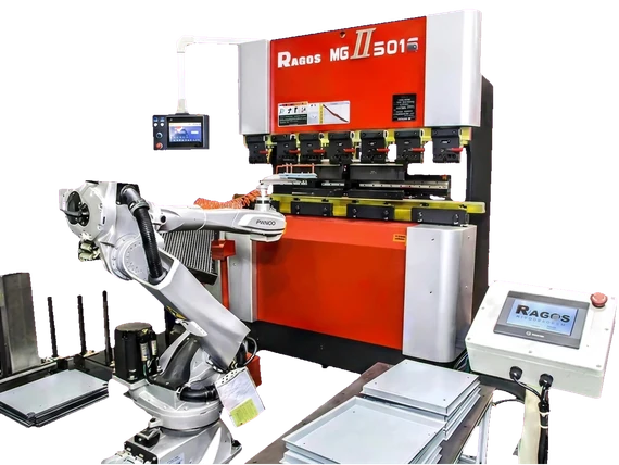
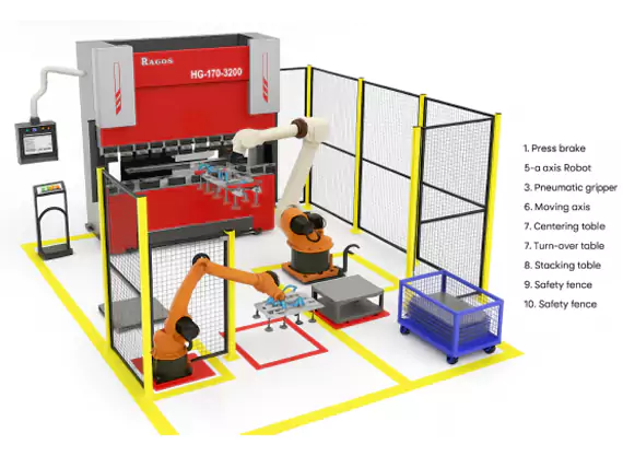
Our robotic bending cell combines a press brake, industrial robot and gripper to handle parts through the bending sequence. The cell layout brings loading, bending, regripping and unloading together around the part.
The cell coordinates a press brake, robot, gripper and controls around one defined part. The blank is loaded, held through each bend, turned or regripped where the sequence requires it, and unloaded. That complete sequence sets which handling tasks and auxiliary stations the project needs.
Read more
The same robot bending cell is assessed on part weight, robot reach and cycle time. In a project it is described as a press brake with robot, with the gripper and regrip station selected for the bend sequence and proposal. Typical work is robotic bending for cabinets, robotic bending for elevator panels and robotic bending for sheet metal parts with several bends.
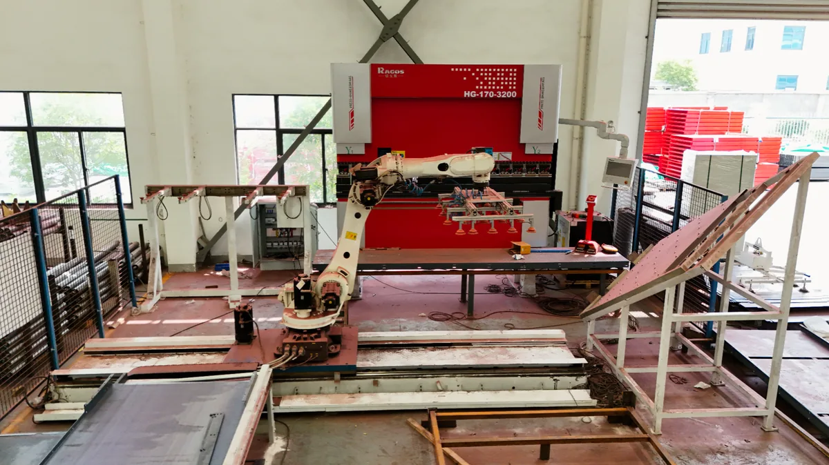
A bending cell installed in the workshop.
Our product information lists a companion press brake range of 40–600 t and FANUC, KUKA, ABB or Yaskawa robot options. Those are catalogue ranges: the specific press brake, robot and achievable part range are confirmed for the project, and the range does not establish that every combination suits a given part.
Equipment overview
Our robotic press brake cell combines a press brake, an industrial robot and a gripper matched to the part. We configure handling, regripping and unloading around the complete bending sequence.
Available configurations
Robotic CNC Press Brake Bending Cell
A robotic bending cell coordinates the press brake, robot, gripper and material-handling stations around the part.
The complete part route comes before the robot brand. Forming capacity, handling load and access are separate checks, and the operations the cell will perform are agreed from them.
Read more
The drawing, material, thickness, bend lengths and intended tooling define the part.
The heaviest and largest blank, gripper mass, center of gravity and robot reach set the handling envelope.
Every bend, turn and grip change is walked through, including clearance from the tooling.
Blank separation, loading, finished-part unloading and the batch and changeover pattern define the interfaces.
Floor space, guarding, operator access and recovery responsibilities belong to the layout.
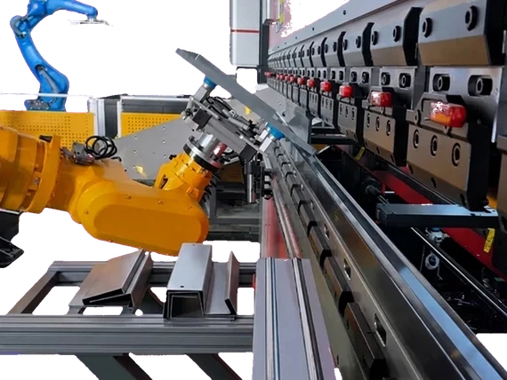
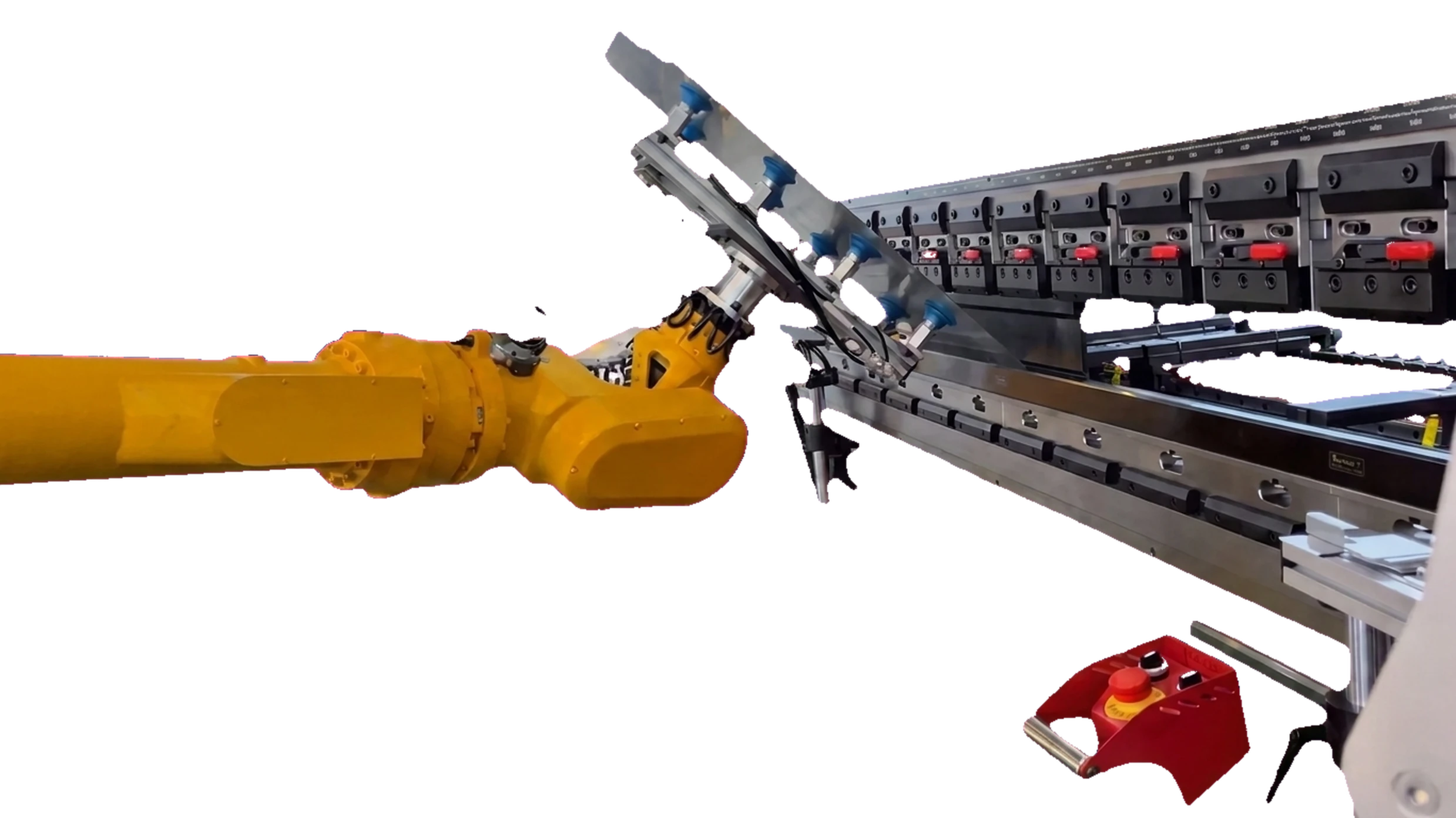
The gripper connects the robot to the sheet and is designed for the part. Its holding force, tooling clearance and contact surfaces must suit every bend; retention and surface marks are checked on representative parts. A grip that works for the first bend can obstruct the next.
Read more
A regrip or repositioning station can support the part while the robot takes a new hold. We select this option where the complete bend sequence requires it, with the fixture and clearances matched to the part. The station and its supply scope are defined in the proposal.
Cell question
What it decides
Part and gripper load
Combined mass, center of gravity, orientation and reach set the handling requirement.
Material, thickness, bend length and tooling
Forming force and press brake capacity are assessed separately from the robot handling load.
Bend sequence
Gripping, turning, tooling clearance and any regrip are reviewed at each bend.
Surface requirement
Contact surfaces are selected and retention and marking are checked on representative parts.
Changeover frequency
Programming, gripper and tooling changes follow the part mix.
Loading and unloading method
Blank separation, alignment, part presentation and finished-part output define the interfaces.
Programming, protection and the project scope
Angle measurement and access protection do different jobs. A selected laser angle measurement system provides feedback for springback correction, and closed-loop operation depends on the measurement system, control compatibility and agreed configuration. A light curtain is one possible protective device. The integrator defines the guarding, interlocks, operating modes, access and recovery procedure for the complete layout.
Read more
3D offline software prepares gripping positions and robot paths away from the machine. The software version and the robot and CNC compatibility belong to the project scope. On-machine commissioning, clearance checks and first-part verification still take place, because offline preparation alone does not remove production stops at changeover.
Companion press brake range in our product information: 40–600 t; the specific machine is confirmed against the part requirements in the project configuration.
Robot options are FANUC, KUKA, ABB or Yaskawa, with the model selected for the full handling load, orientation and reach.
The gripper is part-specific: grip positions, retention, clearance and surface contact are checked on representative parts.
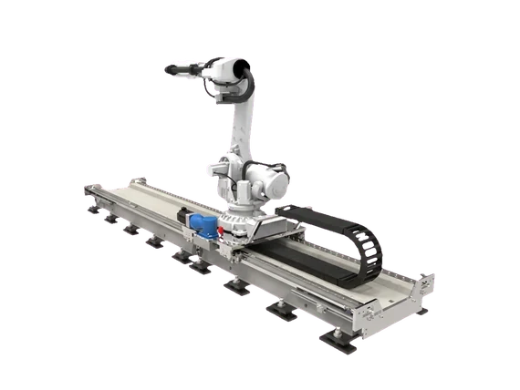
An additional travel axis appears as a 7-axis solution: travel and reach belong to the layout assessment and are not assumed to be included.
A regrip or repositioning station is an option selected for the complete bend sequence and specified in the proposal.
Access protection is designed with the guarding, interlocks and operating modes of the cell safety concept; a light curtain is one option among them.
Laser angle measurement is selected for the material and process, with control compatibility and any closed-loop correction confirmed.
3D offline programming is agreed with software and controller support and includes commissioning and first-part checks.
Automatic loading and unloading is an option: blank separation, alignment and finished-part handling are defined in the supply scope.
Flexible Bending Solution
Cell design starts with part geometry, material, batch volume and bending sequence. The cell can combine FANUC, KUKA, ABB and Yaskawa robots, CNC press brakes and WILA, AMADA or Rolleri tooling; robot, gripper and auxiliary stations must be selected as a coordinated system.
Custom Gripper by JS RAGOS
The end-of-arm gripper is designed around the part, robot and process, from thin sheets to heavier plates, tubes and enclosure assemblies. Grip location, surface contact and load handling must be assessed for bending, welding or automatic loading, with retention and surface protection checked on representative parts.
Bending Cell Layout Overview
The illustrated layout links a loading station, alignment table, press brake, flipping or repositioning station and finished-part unloading area; select these stations for the project. Tool cabinets support organized changeovers; material flow, robot reach and safeguarded access must be assessed together when defining the layout.
7-axis Arrangement with an Additional Travel Axis
A robot with an additional travel axis for positioning along the bending cell, including handling longer workpieces. This arrangement can extend the working area and permit a planned manual operating mode; travel, payload, future part range and safe mode transitions require application-specific validation.
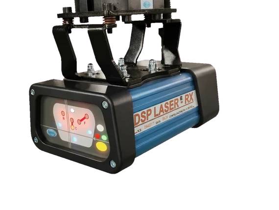
Tool-area Laser Protection
In the protective solution shown in the product information, DSP LASER creates a protection zone that moves with the upper tool. Detection near the closing tools is linked to stopping motion, with protective distance and stopping performance integrated into the machine safety system.
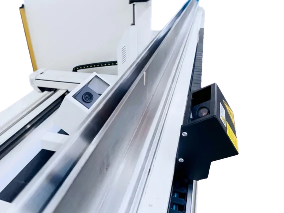
Laser Check Angle Measurement System
A laser projects a line onto the sheet and a camera observes it to calculate the bend angle. Measurement feedback supports correction for springback, linking angle detection with the bending program. Measurement-system selection depends on the material and bending application.
Regrip / Repositioning Station
A flipping or regrip station supports the workpiece while the robot changes its grip or orientation between bends. It enables access to different sides of a complex part; fixtures and locating surfaces must be matched to the part and checked for collision clearance.
3D Offline Software
The software supports gripping and path calculation, interactive adjustment, manual path refinement and vacuum or clamp grippers. Rail travel and stacking setup depend on the quoted configuration; coordinate these with CNC/robot programs in the agreed workflow. Support for KUKA, Yaskawa, ABB, FANUC, Mitsubishi or other controllers must be confirmed for the software version and project.
Applications
Typical applications
Automotive, elevator, cabinet and appliance work can contain repeat part families worth assessing. The categories below are application candidates; suitability follows the actual geometry, material and handling sequence.
Automotive brackets and structural parts
Elevator and escalator components
Electrical cabinets and enclosures
Appliance and HVAC panels
Repeated sheet metal parts with several bends
Resources
Equipment configuration
A configuration covers the press brake, robot, gripper, auxiliary stations, programming and protective integration. The supply scope and the items that need sample validation are set in the specific proposal.
A cell demonstration that can be compared
Read more
Check
Record from the proposal
What it decides
Handling
Part plus gripper mass, center of gravity, reach and regrip sequence
The complete handling load and access are reviewed.
Output
Same drawing, batch, acceptable-part count and elapsed time
Complete cycles are compared, including stops and recovery.
Quality
Unloaded angle, flange dimensions and cosmetic checks on identified samples
Formed-part results are kept separate from robot positioning claims.
Recovery
Documented response to a missed pick, dropped part or interrupted cycle
A safe recovery procedure is agreed with the cell integrator.
Manufacturer product range and project configuration
Parameter
Value
Companion press brake range — specific machine by project
40–600 t
Robot options — model by handling load and reach
FANUC / KUKA / ABB / Yaskawa
Gripper — matched to part and sequence
Custom by JS RAGOS
Programming — software and controller support to agree
3D offline software
Options — selected in the project integration scope
The listed range and features are not a standard bill of materials. The machine, auxiliary stations, software, protective integration and part validation requirements are agreed in the project configuration.
RAGOS product data, 2026-11-01; confirm current configuration with our team.
Common questions
How long does a robotic bending cell take to pay back?
Payback depends on the part, batch size, shift pattern and labor cost, so no fixed figure applies without production data. The cycle time and changeover assumptions are reviewed against the production data for the specific case.
Can the cell handle mixed parts?
Mixed parts need a review of geometry, grip positions, tooling, programs and changeover work. A gripper or tool change may be needed; offline programming and a quick-change strategy can support the agreed part family but do not establish suitability on their own.
How many operators does the cell need?
The robot can take over agreed handling tasks, while material supply, inspection, changeover and fault recovery still need assigned responsibility. Staffing follows the validated process and shift plan; a robot alone does not establish an unattended shift.
How is a robot press brake programmed?
3D offline software can prepare the bend and robot sequence. Software and controller support are confirmed, the paths are commissioned on the cell, clearance is checked and the first part is verified before production.
What safety devices are included?
The project safety design defines the guarding, interlocks, operating modes and access and recovery procedures. A light curtain or tool-area protection device is selected and integrated for that layout; it is not a substitute for the complete cell assessment.
Can you automate an existing press brake?
It depends on the press brake model, control and condition. The machine details and the part drawing establish whether it can be integrated or whether a matched press brake is needed.
Documents, sources and next steps
Related equipment and electrical cabinet applications
Press brakes, panel benders, V-grooving machines and robotic bending cells: 6 series and 80 models with standard specifications and the configuration choices behind a machine order.
English PDF · 28 pages · 80 models · 6 series · 1.64 MB · November 2026