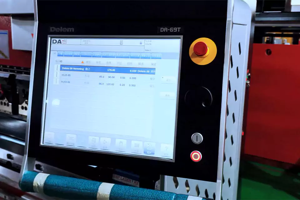
Delem DA-69T
A Delem touchscreen interface for bending programs and job settings.
MG SERIES · UP-ACTING PRESS BRAKE
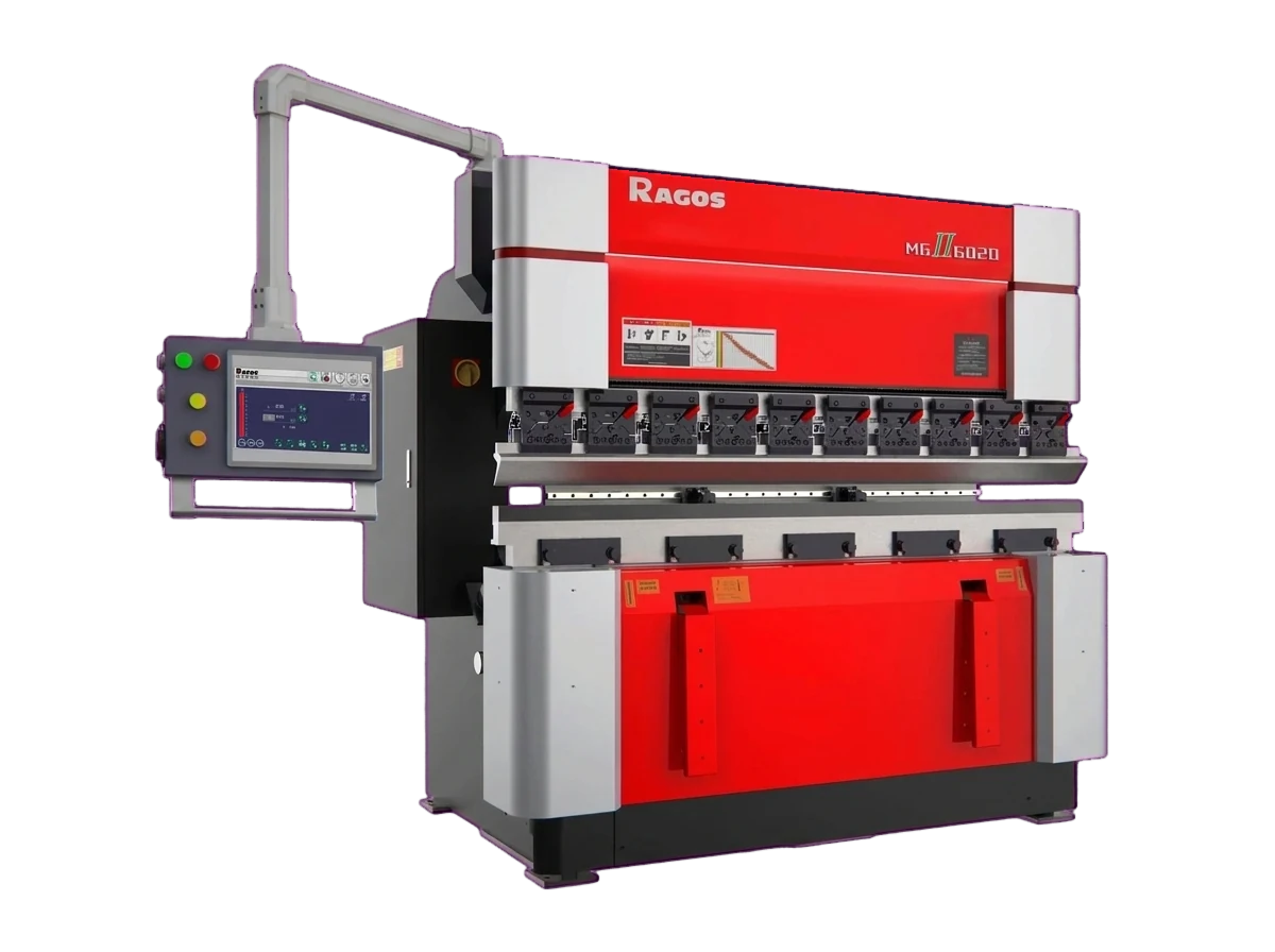
A rising table press brake — also called an up-acting press brake or upacting press brake — has a fixed upper beam, a rising lower table and CNC control across five MG models. The MG up-acting press brake is a CNC up-acting press brake; in this arrangement the lower table moves up to complete the bend rather than the upper beam moving down.
UP-ACTING BASICS
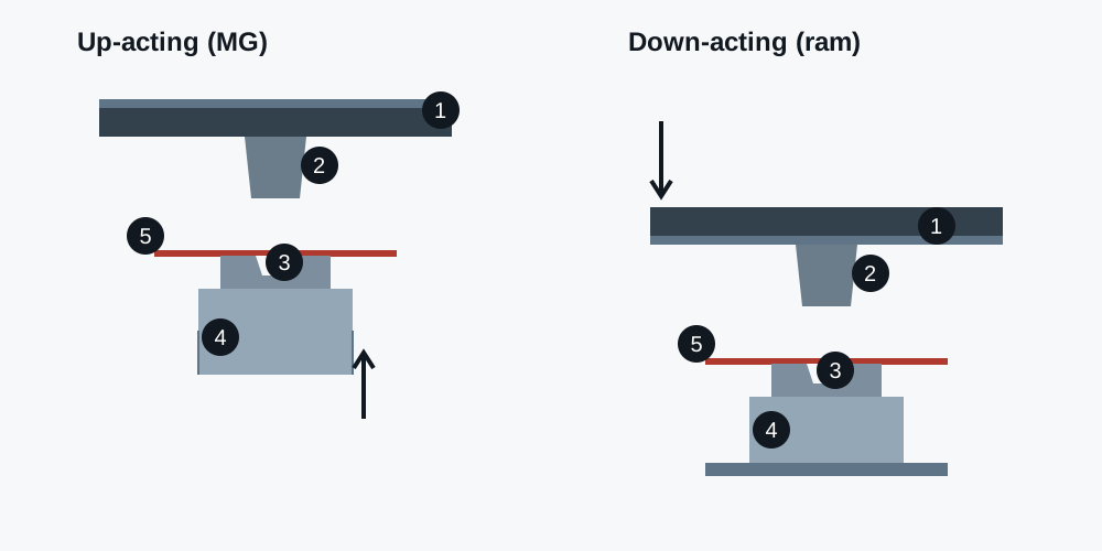
The MG completes the bend by raising the die towards a fixed punch. That choice decides how the sheet is loaded, supported and checked — not only which way the beam moves.
In the MG series the upper beam stays fixed, with the punch clamped to it. The lower table carries the die and rises through the stroke. The sheet rests on the die and travels upward with it, while the punch remains the reference above.
For a buyer, the structure matters in three places: where the sheet is loaded, how the part is supported while the table rises, and which clearances have to be checked before a model is chosen. Each is covered below.
The term describes motion, not drive or control. An up-acting machine can use a hydraulic or hybrid drive, and a down-acting machine can be electric. Motion, drive and control level are separate questions, each with its own evidence in the quotation.
The parts that fit this arrangement are loaded flat and formed with the die rising: duct flanges and brackets, cabinet and enclosure panels, and elevator door or frame components. The deciding questions are the part length, the return flange, the support during the stroke and the batch pattern, not the industry name.
| Aspect | Up-acting (MG) | Down-acting ram |
|---|---|---|
| Element that moves | Lower table with the die | Upper beam (ram) with the punch |
| Element fixed in the stroke | Upper beam with the punch | Lower bed with the die |
| Sheet during the stroke | Rises with the die | Stays at bed level |
| Tooling reference | Punch height fixed; the die moves | Die height fixed; the punch moves |
| Support during the stroke | Support must follow the rising table | Support stays at bed level |
| First dimensions to check | Throat depth, opening height, stroke, support plan | Ram travel, opening, bed and support |
Both arrangements can produce an accurate bend. Angle and repeatability depend on frame and table stiffness, tooling condition, crowning or deflection compensation, control and setup; check them as separate items rather than reading them from the direction of motion.
CONTROL OPTIONS
Bending programs and job settings in a graphical machine interface.
A Delem touchscreen interface for bending programs and job settings.
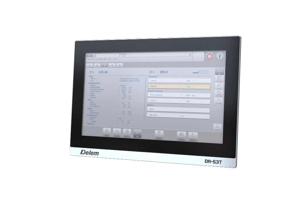
Delem control with a graphical bending interface.
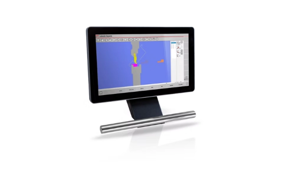
ESA control with a graphical bending display.
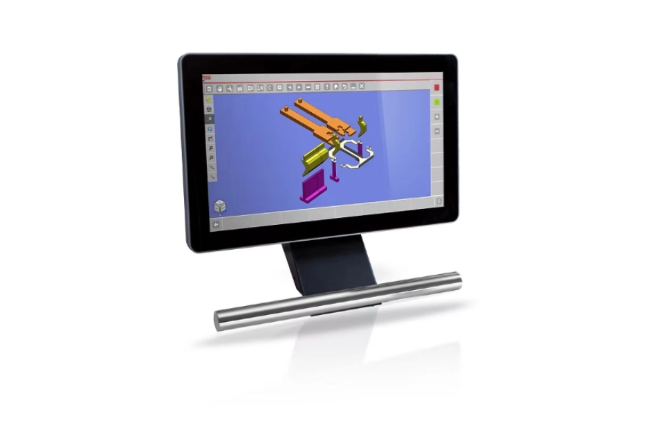
ESA control with a three-dimensional bending display.
SHEET POSITIONING
CNC positioning for successive bends, with the fingers, guide rails and support structure shown in detail.
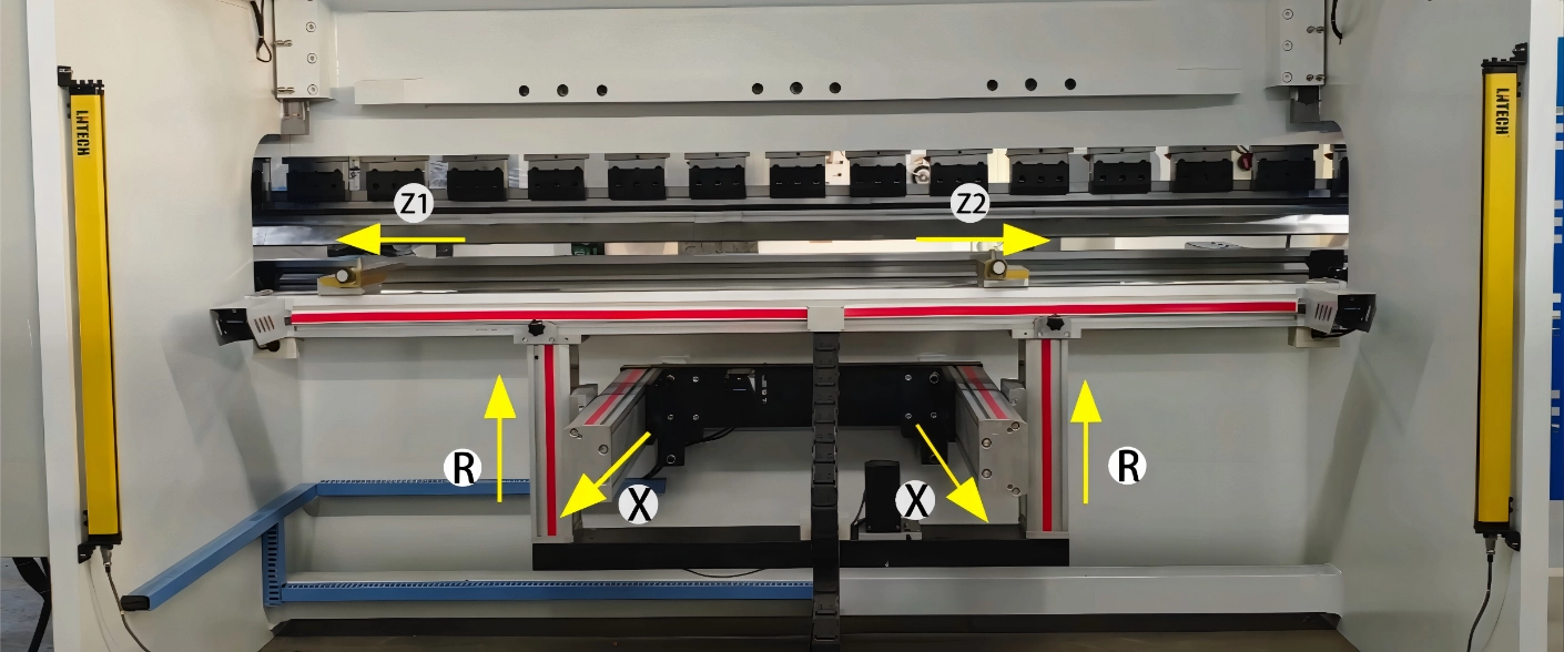
Positions the sheet for successive bends. Axis travels and support arrangements follow the machine configuration.
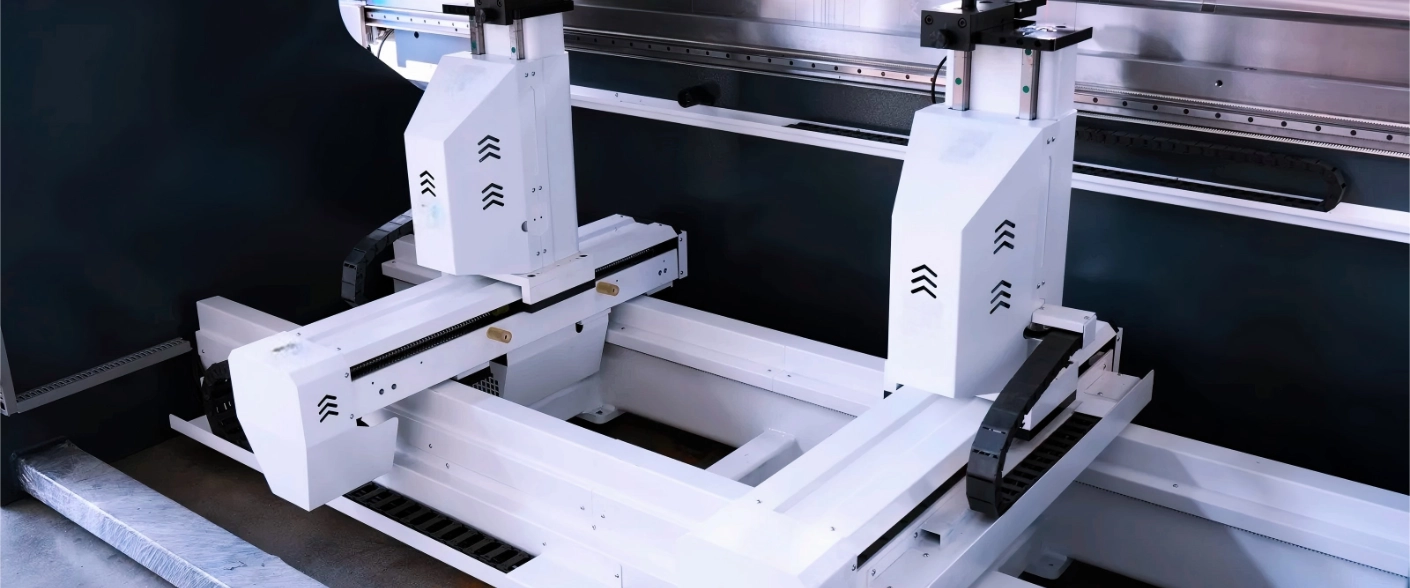
A clear view of the stop fingers, guide rails and support structure used for sheet positioning.
SMART BENDING
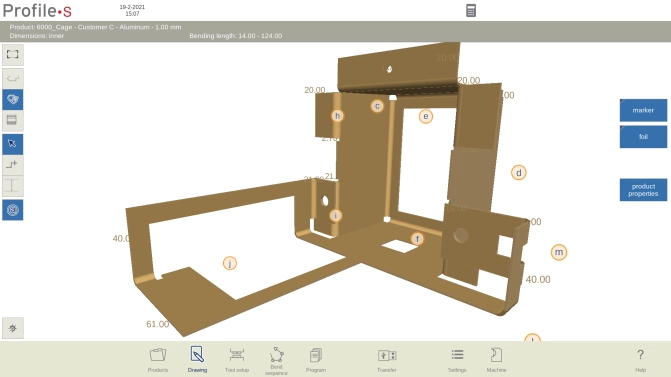
Prepare bending sequences, tooling and interference checks away from the machine.
DRIVE CONFIGURATION
Drive selection follows the machine architecture, load and working cycle.
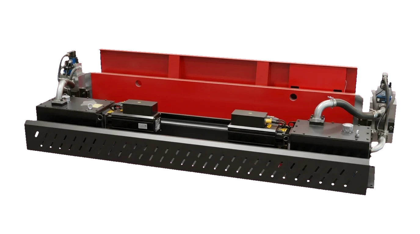
A hybrid drive option in the RAGOS configuration library.
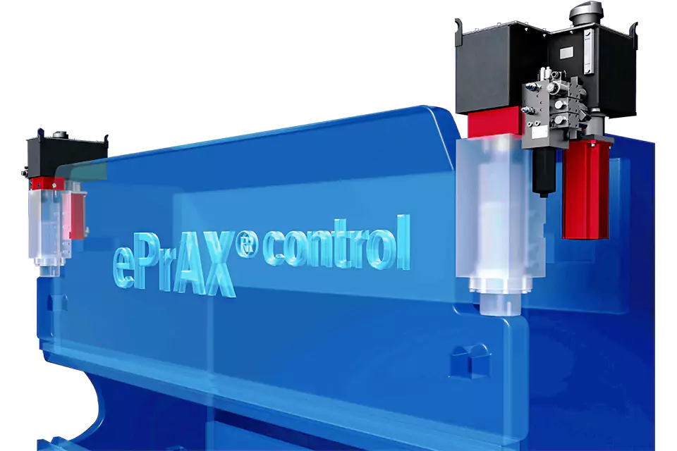
A hybrid drive option with the HAWE ePrAX system shown in the configuration library.
TOOL HOLDING
Clamp and holder options for the selected tooling interface.
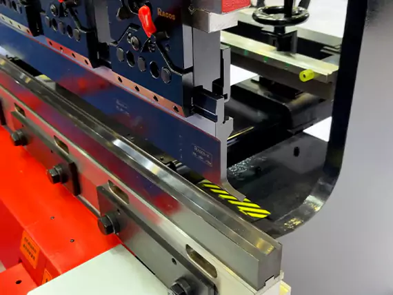
The illustrated MG holder secures the punch with a lever, without a separate tightening tool.
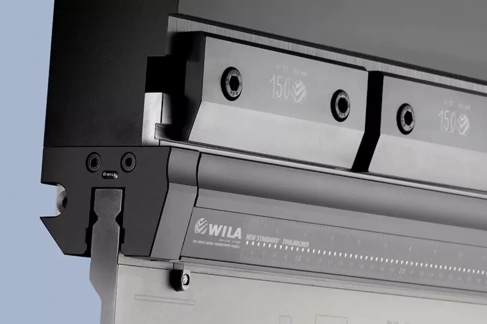
Hydraulic clamping with the WILA tooling interface shown in the configuration library.
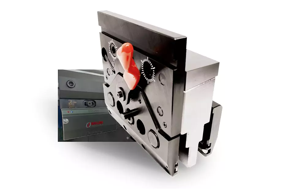
Mechanical clamping with the Amada SGRIP holder shown in the configuration library.
WORKPIECE SUPPORT
The follow-up support device carries the sheet through the bending motion. Its dimensions, load and synchronization are selected for the application.
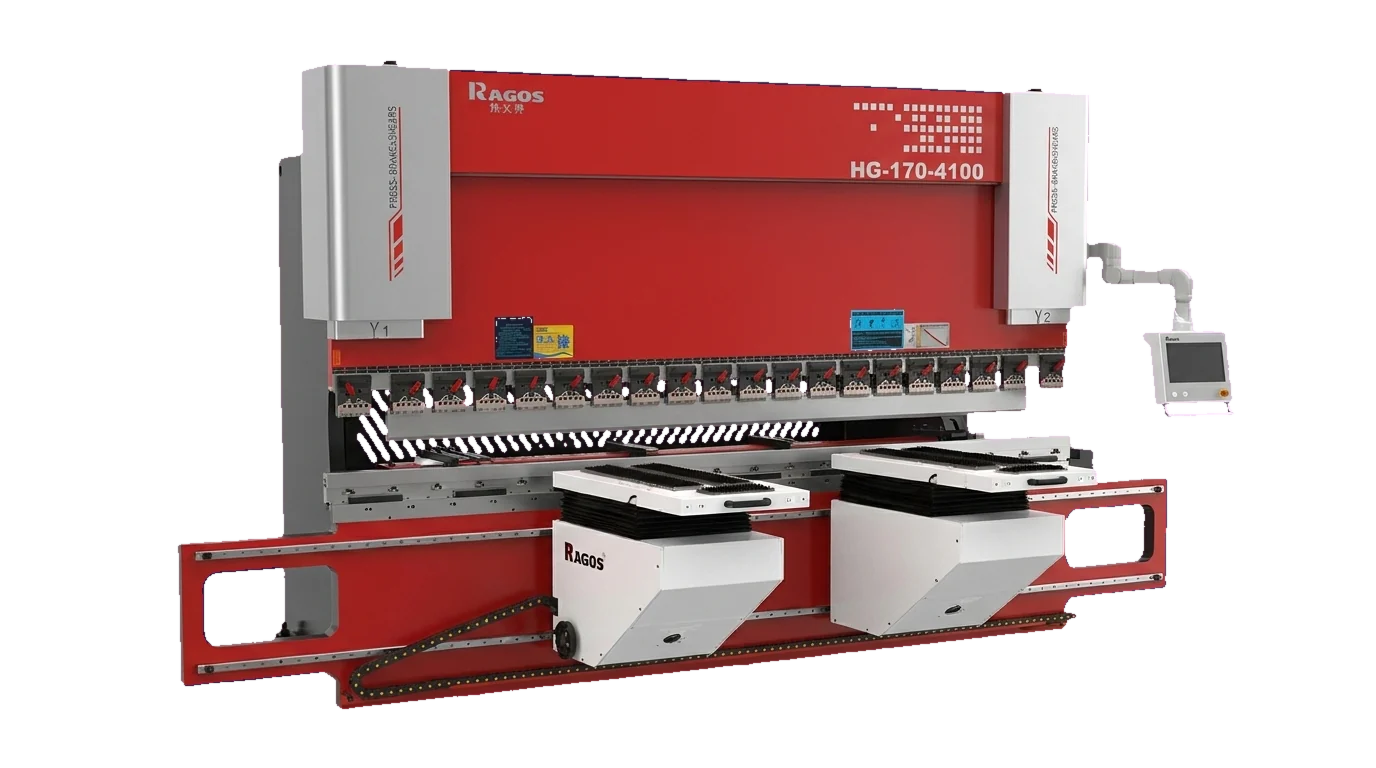
Supports the workpiece during bending.
Follows the bending sequence.
ROBOTIC BENDING
Pair MG bending with robotic handling, part storage and positioning in an integrated bending cell.
Explore robotic bending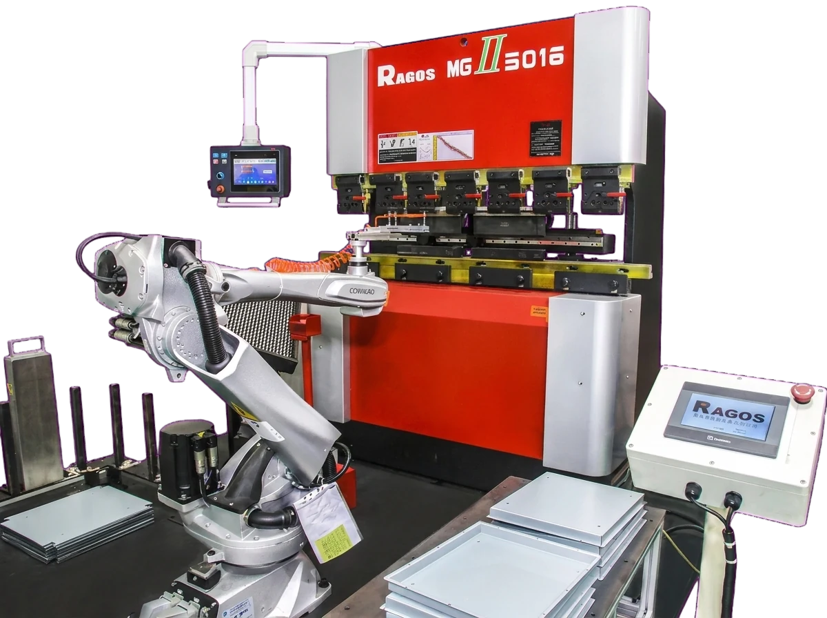
TOOLING SYSTEM
Punches, dies and clamping are matched to the machine and the forming requirement.
PART TO MODEL
The model table answers once the force and the bend length are known. Work through the part in this order; the example below uses one bracket to show the arithmetic.
Estimate the air-bending force from material tensile strength, actual thickness, bend length and V-die opening. Our tonnage calculator uses the same formula as the reference table.
Match force and bend length to one row. A model has to cover both values; the next model down cannot be used by shortening the bend.
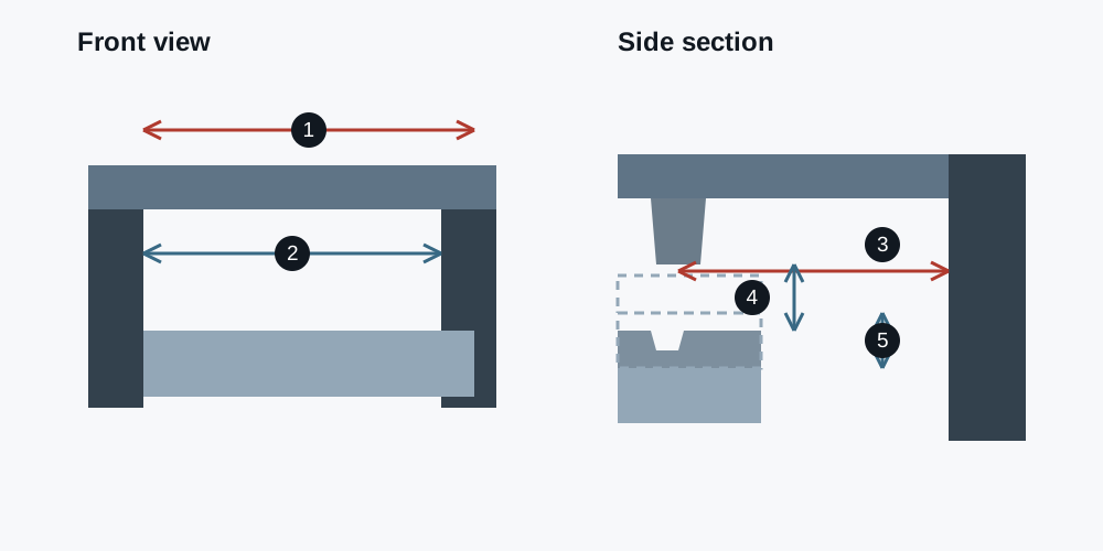
Check throat depth against the return flange, and opening height and stroke against the tool set and the part.
Confirm the tool load per metre, the V-die opening and how the part will be supported while the table rises.
| Check | What to compare | Where to read it |
|---|---|---|
| Force | Part force estimate against rated force | Model table, rated bending force column |
| Length | Part bend length against bending length | Model table, bending length column |
| Reach | Return flange against throat depth | Model table, throat depth column |
| Space | Tool set plus part height against opening height | Model table, opening height column |
| Travel | Tool change and part removal against stroke | Model table, stroke column |
This is an air-bending estimate for one material and one V opening, not a trial-bend result. Tool load per metre, off-centre loads and the final tooling still need checking; confirm the ton convention in the quotation.
TECHNICAL DATA
Five MG models. Compare the up-acting press brake tonnage and bending length side by side, with the complete catalogue parameters.
| Model | MG-1003 | MG-8025 | MG-6020 | MG-5016 | MG-3512 |
|---|---|---|---|---|---|
| Rated bending force (ton) | 100 | 80 | 60 | 50 | 35 |
| A — Bending length (mm) | 3100 | 2500 | 2000 | 1600 | 1200 |
| B — Distance between frames (mm) | 2550 mm | 2090 mm | 1700 mm | 1220 mm | 1020 mm |
| C — Throat depth (mm) | 405 mm | 405 mm | 405 mm | 405 mm | 300 mm |
| E — Daylight opening (mm) | 390 mm | 390 mm | 390 mm | 390 mm | 390 mm |
| D — Y-axis stroke (mm) | 100 mm | 100 mm | 100 mm | 100 mm | 100 mm |
| Approach speed (mm/s) | 52 mm/s | 52 mm/s | 52 mm/s | 52 mm/s | 52 mm/s |
| Bending speed (mm/s) | 10 mm/s | 10 mm/s | 10 mm/s | 10 mm/s | 10 mm/s |
| Return speed (mm/s) | 46 mm/s | 46 mm/s | 46 mm/s | 46 mm/s | 46 mm/s |
| Machine length (mm) | 3130 mm | 2650 mm | 2720 mm | 2210 mm | 1910 mm |
| Machine width (mm) | 1450 mm | 1350 mm | 1510 mm | 1510 mm | 1510 mm |
| Machine height (mm) | 2480 mm | 2320 mm | 2400 mm | 2270 mm | 2270 mm |
| Main motor power (kW) | 7.5 kW | 7.5 kW | 5.5 kW | 4.0 kW | 3.0 kW |
| Hydraulic cylinders | 3 pcs | 3 pcs | 3 pcs | 1 pcs | 1 pcs |
| Oil tank capacity (L) | 72 L | 55 L | 45 L | 40 L | 33 L |
| Machine weight (kg) | 6600 kg | 4300 kg | 3500 kg | 2800 kg | 2200 kg |
Rated force uses the catalogue notation ton; confirm the unit convention and kN equivalent for the selected model before comparing calculated force.
COMMON QUESTIONS
A press brake whose lower table, carrying the die, rises towards a fixed upper beam and punch. The MG series uses this arrangement; the sheet rests on the die and moves upward during the stroke.
In a down-acting machine the upper beam moves down towards a fixed bed. The bend is the same operation; the difference is which element moves, where the sheet sits during the stroke and how it has to be supported.
There is no single thickness limit. Force depends on material, thickness, bend length and V-die opening, so the same machine bends a longer part in thinner sheet or a shorter part in thicker sheet. Estimate the force and compare it with the selected model row.
Choose the smallest model whose rated force and bending length both cover the part, then check throat depth, opening height and stroke. The worked example on this page shows the sequence for one bracket.
Model, controller, backgauge axes, tooling, clamping, support and any automation change the scope. Price is confirmed against a quotation for the selected configuration rather than a catalogue figure.
Yes, as a configured bending cell. Robot integration, guarding and material flow are defined per project; the photograph on this page shows a demonstration arrangement, not a standard package.
REQUEST A QUOTE
Choose a model and talk with us about the controller, tooling, price and equipment configuration for your quotation. The same review applies to an up-acting press brake for cabinets or an up-acting press brake for elevator panels.
OTHER SERIES
Compare other RAGOS bending equipment.
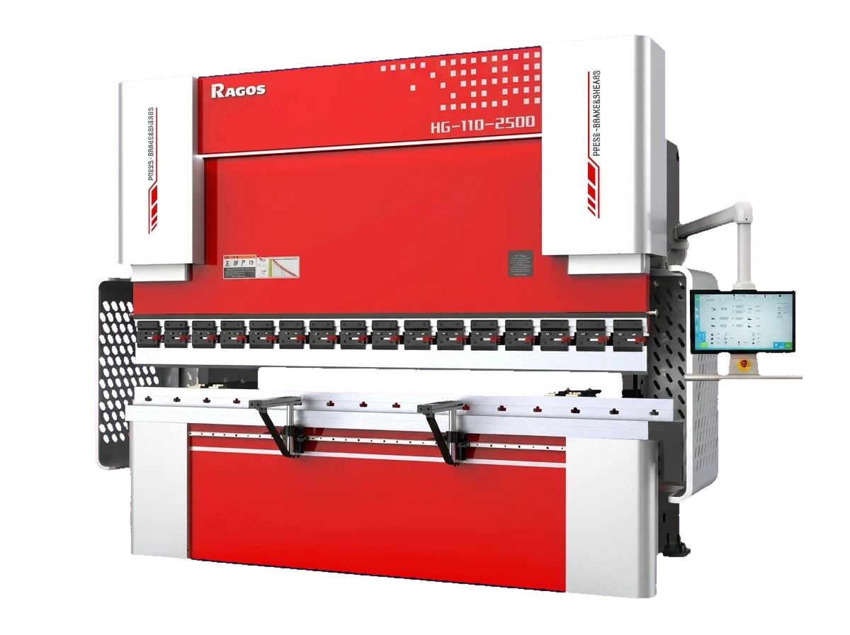
Electro-hydraulic press brakes across a broad model range.
View equipment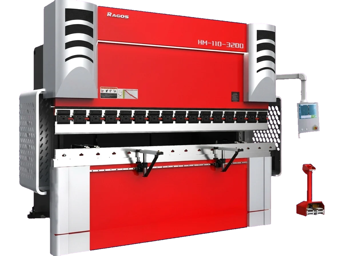
Electro-hydraulic machines with long-worktable models.
View equipment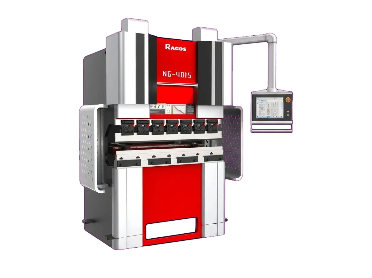
Servo motors and mechanical transmission without a hydraulic drive.
View equipment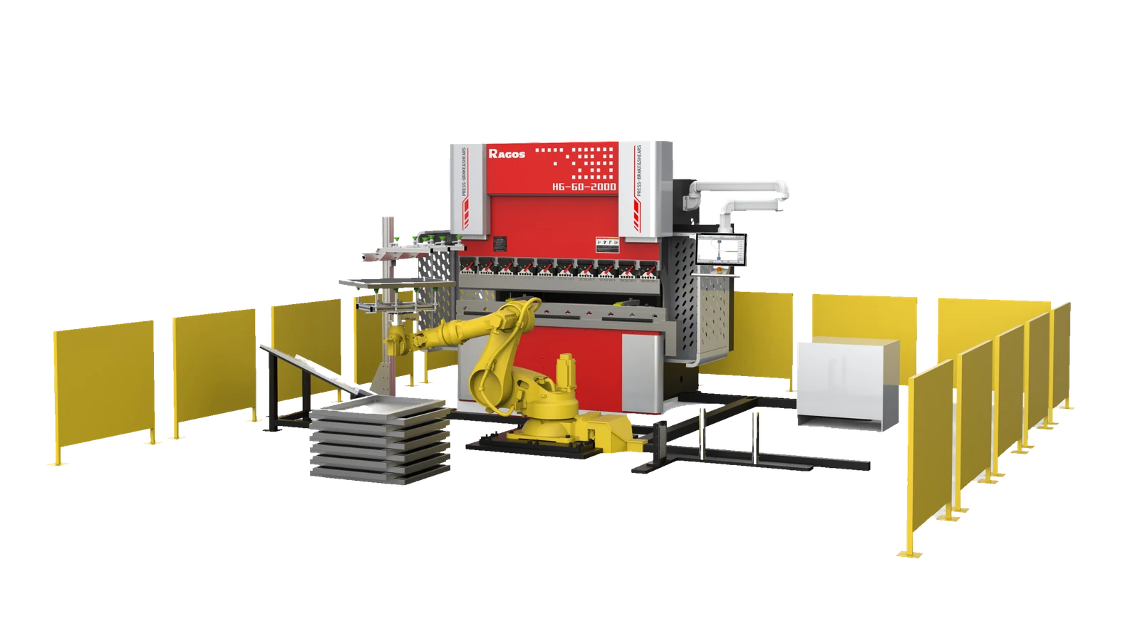
Press braking integrated with robotic handling and positioning.
View equipment