Start with the complete part and handling sequence
Choose bending automation in two steps: establish whether the complete part and handling sequence can be defined and verified, then compare accepted output and installed cost. A feasible sequence does not by itself justify an investment. If gripping or a bend remains unresolved, return to the tooling, process or route assessment.
Keep the manual process as the comparison baseline. Record representative drawings, material and actual thickness, blank weight, contact surfaces and surface requirements. Follow each bend, turn, locating step and any change of grip, together with the repeat-order and changeover pattern.
Verify forming capacity and handling separately: the machine and tooling must make each bend, while the robot must grip, turn and locate the part through the full sequence.
Review the process and forming-force requirement separately: Bending process / Tonnage estimate
Compare feasible bending routes
A short batch alone does not rule out automation. Compare preparation, programming, changeovers and accepted output for the actual work mix; there is no universal batch threshold.
| Route | When to compare | What to verify / when to pause |
|---|---|---|
| Manual baseline | Changing work or steps that still require operator positioning and judgement | Measure support, turning, gauging, quality and changeover work on the complete part. |
| Handling assistance | The operator still positions and judges the part, but handling or support needs improvement | Confirm the actual support or handling device, load, travel and workflow; this is not a statement of an available RAGOS package. |
| Robotic press brake cell | A defined part family with potentially repeatable gripping and handling | Verify every bend, locating point, turn, regrip and changeover. Pause this route if retention or clearance is unresolved. |
| Panel-bending route | Multi-edge panels that may suit clamping and edge folding | Verify grip, access to every edge, repositioning and finished-part removal. This is a separate forming route, not a component added to a robotic press brake. |
Review the proposed equipment after screening the route: Robotic cell scope / Panel bender scope
What a bending cell contains
The robot is only one item in the cell. A working installation usually includes the press brake with its control, a robot mounted on a base, a gripper or a set of grippers, a part presentation table or a stack, a finished-part station, guarding and safety devices, and software that generates the robot path from the bend program. Each item has to match the others, and the weakest item sets the cell output.
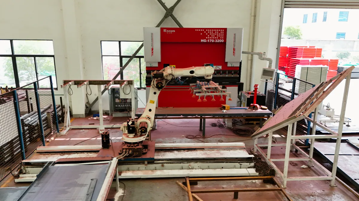
- The press brake has to expose a control interface that the cell can command, not only a manual control panel.
- The gripper has to suit the part family: a vacuum gripper, a magnetic gripper and a mechanical gripper solve different surfaces and shapes.
- Verify reliable sheet separation and alignment; double sheets can create collision, damage and rejected-part risks.
- The finished-part station has to accept the part without damage and without a manual sort at the end of the shift.
- Confirm with the integrator the permitted operating modes, protective measures and any change to manual operation; stopped automatic operation does not establish that manual cycling is permitted.
- The programming environment has to produce a path that matches the tooling and the bend sequence, or the cell will need constant manual correction.
Interfaces between robot and press brake
The interface is where many cells fail in practice. The robot and the press brake have to agree on when the ram may move, when the sheet is in position, when the bend is complete and when the part can be removed. That handshake can be a small set of digital signals or a fieldbus connection with a richer data exchange. The important question is not which protocol is used, but whether the press brake control can select a program, report its state and accept an external command without an operator at the panel.
- Program selection: the cell has to choose the bend program for the part without manual entry.
- State signals: the cell has to know whether the ram is at the top, at the bottom or in a fault state.
- Safety coordination: distinguish authorised coordinated robot-and-ram bending from access and fault recovery; the integrator must define and validate the permitted motion and protective functions for each operating mode.
- Tooling reference: a tooling change has to be reflected in the cell program, not only in the press brake.
- Fault recovery: a stopped cell has to be restartable without losing the part position or the sequence.
- Data: part counts, cycle times and fault codes should be available to the shop, or the cell cannot be managed.
Check cycle time, changeovers, recovery and labor requirements
Record simulated, estimated and actual-trial data separately. A simulated cycle is not a measured recovery time or an accepted-part count. Use the same drawing and timing boundaries for comparisons.
| Quantity | Why it decides the case |
|---|---|
| Cycle time per bend, manual and automatic | Record the complete part cycle and accepted parts; a per-bend time difference is not a net saving. |
| Number of bends per part and parts per batch | Record bends, batch size, preparation and programming for the actual returning work. |
| Changeover time, including tooling and gripper changes | Include tooling, gripper changes and first-part verification. |
| Uptime and fault recovery time | Record available time, stops and recovery; compare observed losses rather than assuming one route loses more. |
| Part family commonality | Check the proposed grippers and programs across representative members of the family. |
| Floor space and operator ratio | Record space and actual operator time for supply, loading, inspection, changeover and recovery; do not assume a staffing ratio. |
Common reasons a cell underperforms
- The part family is wider than the gripper and the programs were designed for.
- Changeover was underestimated, so the cell runs well on one job and poorly on the next.
- The press brake cannot be commanded from the cell, so an operator still stands at the panel.
- The sheet presentation allows double sheets or misaligned parts, and the cell stops to recover.
- The robot path was taught by hand for one part and does not transfer to the family.
- Safety guarding was added late and reduced the working envelope or the operator access.
Prepare part drawings and production records for selection
Send representative and difficult-part drawings with revision, material, actual thickness, weight, surface requirements and batch/changeover records. For a retrofit, include the machine model, control, condition and interfaces. Ask the proposal to separate confirmed scope from unresolved items. Review every bend and grip change, then agree an actual-material complete-part trial and recovery validation with the responsible integrator; simulation alone is not a trial record.
Press brake capacity and tooling
Review candidate machines; cell compatibility requires project confirmation.Agree acceptance records
Define sample, measurements and complete-process checks before acceptance.
Compare accepted output, not motion speed
Use the same part family and drawing revision for manual and automatic trials. Define the observation window in advance and record accepted parts, rejects, programming, changeover, planned stops, recovery time and the operator time actually required. Good parts per scheduled hour includes these losses; a robot motion cycle alone does not.
For a simple payback comparison, use the same accepted-part quantity for both routes and do not monetize extra output. Subtract robot-route annual cost from manual annual cost, then divide positive incremental installed investment by positive annual net benefit. Keep assumptions visible and show a lower-demand scenario. Use the robotic bending-cell cost and simple payback calculator to compare your inputs.