Look at a freshly cut plate. Its outline may look correct while its cut face slopes through the thickness. The face may look smooth while solidified metal remains attached underneath. These are different issues. ISO 9013 provides a framework for specifying the geometrical quality of thermal cuts; a useful order identifies the required features, and inspection checks each one.
Begin with the edge you can see
First distinguish the top of the plate, the cut face through its thickness and the lower edge. The next operation helps identify what matters: mating parts need the specified geometry and dimensions; an exposed face needs an agreed surface requirement; welding or coating may call for separately specified edge preparation.
- The cut face: how far it departs from the intended direction through the plate.
- The surface of that face: how tall and how regular the profile irregularities are.
- The lower edge: whether re-solidified material stayed attached after the cut.
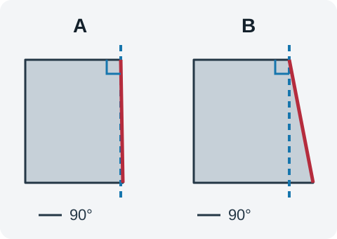
Two different questions: how straight the cut is and how smooth it is
Face deviation asks how far the face departs from its designed direction. Roughness describes small-scale height variations on that face. Sketch A is close to the square-edge target; B leans away from it. A deliberately designed weld bevel has an inclined target, so it must be assessed against that target rather than automatically against 90°.
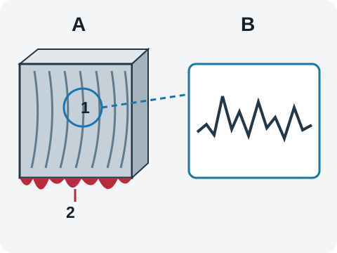
In the next sketch, 1 marks the face texture and 2 marks dross attached to the lower edge; B enlarges the surface profile. Agree the required condition of that lower edge with the next operation. Warping of the plate is a separate flatness issue, addressed through the applicable material and drawing requirements.
What can a photograph tell you?
A photograph helps both parties identify the same edge and mark visible dross or inclination. Viewing angle, lighting and scale affect an ordinary photograph, so it does not replace u or Rz5 measurements made by the specified method. Link the photograph number to the measurement record.
What do u and Rz5 measure?
u is the perpendicularity or angularity tolerance characteristic, expressed in mm, for the cut face relative to its specified direction. It is not an angle in degrees or simply the slope seen in a photograph. Rz5 is a profile-height parameter in µm describing surface roughness. Use the evaluation appropriate to that parameter rather than substituting an Ra reading. Confirm the sampling region, instruments and evaluation method against the applicable text and inspection plan.
A quality range concerns a particular characteristic and must be read with the thickness and applicable conditions. If a supplier quotes a range or class, establish whether it concerns u, Rz5 or dimensional tolerances. A single part can have different requirements for these features; a lower roughness reading cannot offset excessive deviation in another characteristic.
Worked example: a straight laser cut in 6 mm-thick steel plate
This is a teaching scenario: all requirements and readings are invented for explanation, not ISO range limits, recommended tolerances or factory measurements. Assume drawing CQ-DEMO-01 revision A, 6 mm steel and straight-edge laser cutting. The parties have confirmed applicable methods, positions and conditions and agreed u≤0.30 mm and Rz5≤60 µm. Two inspection records, A and B, are then available.
| Item | Assumption used for this example | Record A | Record B | What the comparison shows |
|---|---|---|---|---|
| Geometrical deviation u | u not greater than 0.30 mm | u = 0.24 mm | u = 0.36 mm | B exceeds the limit by 0.06 mm; A is within it |
| Roughness Rz5, agreed example limit | Rz5 not greater than 60 µm | Rz5 = 52 µm | Rz5 = 48 µm | Both readings are below the example limit |
- Read the u row first: A gives 0.24≤0.30. For B, 0.36−0.30=0.06 mm, so this characteristic exceeds the example requirement.
- Then read the Rz5 row: both 52 and 48 are below 60 µm. B has the lower roughness reading, but that does not cancel its excessive u value.
- A completes only these two example comparisons. Dimensions, dross removal and other order requirements still need their own checks. Confirm missing requirements; obtain missing measurements.
An order record can follow this structure: “CQ-DEMO-01 / revision A; 6 mm steel; straight-edge laser cutting; standard edition and amendment: [confirm]; u and Rz5 requirements: [the example values]; inspection plan and locations: [confirmed document]; dimensions and edge preparation: [separate requirements].” Complete the bracketed fields before using a record for an actual order.
What the published summary of the scope covers
The ISO public abstract states the following thickness ranges. These describe the standard’s scope, not the capacity of a particular machine. It separately requires agreement when applying the document exceptionally to other cutting processes, and directs flatness matters to the relevant material standards.
| Cutting process in the published summary | Thickness range stated there |
|---|---|
| Oxyfuel cutting | 3 mm to 300 mm |
| Plasma cutting | 0.5 mm to 150 mm |
| Laser cutting | 0.5 mm to 32 mm |
For example, 40 mm laser cutting falls outside the laser thickness range listed here. Review the applicable technical specification, requirements and validation basis instead of assuming that quoting the standard establishes applicability. A supplier’s maximum cutting thickness is also not evidence of cut quality.
From agreed requirements to an inspection decision
- Before ordering: identify mating, welded or exposed edges and agree the drawing revision, characteristics, requirements and standard edition.
- Before measuring: the inspector checks specimen identity, actual thickness, evaluation region, support and surface condition against the agreed plan, using instruments suitable for the characteristic and requirement. Do not remove an anomaly by grinding and then describe the result as the original cut.
- When recording: connect each value with its feature, unit, location and method. Use photographs to identify locations and visible defects while recording geometry and roughness separately.
- For an excessive reading: first check units, method and the record. Once confirmed, agree remeasurement, rework or another disposition. Keep a separate record of measurements after rework so the original evidence remains available.
A requirement nobody recorded cannot be inspected. Write the order information once and keep it with the measurements, so a later question about conditions can be answered without guesswork. The worksheet further down this page produces exactly this list as plain text, with blank fields marked "to confirm".
| Item to record | How to record it | Who confirms it |
|---|---|---|
| Part or drawing number, with revision | Copy the number and the revision you actually work to | Buyer and supplier |
| Material grade, ordered and actual thickness | Keep the ordered specification and record the measured thickness with its unit | Buyer specifies; supplier/inspector records actual values |
| Process, machine and setup | Cutting process, and the machine and setup actually used | Supplier |
| Standard edition and amendment | Identify the base edition, amendment inclusion and applicable inspection plan | Both sides |
| Agreed requirement and unit | The limit and its unit, for example millimetres for skew or micrometres for roughness | Both sides |
| Method, instrument and position | How the reading is taken and where on the part | Both sides |
| Measurement conditions | Environment, part support and instrument state at the time of reading | Both sides |
| Reading with unit, or open item | The measured value with its unit, or "to confirm" and the responsible person | Supplier |
Each record ends the same way: a value with a unit, or an explicit open item. A missing value is information too, as long as it is written down as missing.
Edition, publication dates and official access
- Number
- ISO 9013:2017 + ISO 9013:2017/Amd 1:2024
- Name
- Thermal cutting - Classification of thermal cuts - Geometrical product specification and quality tolerances
- Status
- Current
- Base edition published
- February 2017
- Amendment published
- September 2024
The reference "ISO 9013:2017 + ISO 9013:2017/Amd 1:2024" means the 2017 base document plus its separate 2024 amendment. They are published as two entries, so both must be consulted, and an order should say explicitly whether the amendment is included. Ask the issuing body or an authorised distributor for the controlled text; the tables of classes, limits and methods belong there, not on this page.
Where can you verify and obtain the documents?
The ISO links below identify the 2017 base edition and the 2024 amendment and lead to official acquisition information. The Kjellberg and Hypertherm pages explain cut-face features and measurement context; their product performance claims do not establish a result for this order.
Reference check record
- Status checked
- 2026-11-07
- ISO metadata checked
- 2026-11-07